makeflyeasy PixPilot-C3
The PixPilot-C3 is a low cost flight controller with fully redundant IMUs. In most cases, an onboard compass is more susceptible to interference, so we removed the onboard compass and used an external compass instead. Integrated high gain buzzer. The PixPilot-C3 flight controller is sold by a range of resellers listed on the makeflyeasy(http://www.makeflyeasy.com)
Specifications
Processor:
32-bit STM32F427VIT6 ARM Cortex M4 core with FPU
168 Mhz/256 KB RAM/2 MB Flash
32-bit failsafe co-processor (STMF103)
Sensors
TWO redundant IMUs (accels and gyros)
Gyro/Accelerometers: two ICM42688-P(SPI)
Barometers: Two redundant BMP388 barometers
Power
Redundant power supply with automatic failover
Power supply 4V-6V
Interfaces
14x PWM servo outputs (8 from IO, 6 from FMU)
S.Bus servo output
R/C inputs for CPPM, Spektrum / DSM and S.Bus
5x general-purpose serial ports
2x I2C ports
2x CAN Bus interface
MicroSD card reader
Type-C USB
High-powered piezo buzzer driver
Safety switch / LED
Servo rail BEC independent power input for servos
Dimensions
Weight 40g
Size 74mm x 45mm x 16mm
UART Mapping
SERIAL0 -> console (primary mavlink, usually USB)
SERIAL1 -> USART2 (telem1,DMA-enabled)
SERIAL2 -> USART3 (Telem2,DMA-enabled)
SERIAL3 -> UART4 (GPS1)
SERIAL4 -> UART8 (GPS2,DMA-enabled)
SERIAL5 -> UART7 (USER)
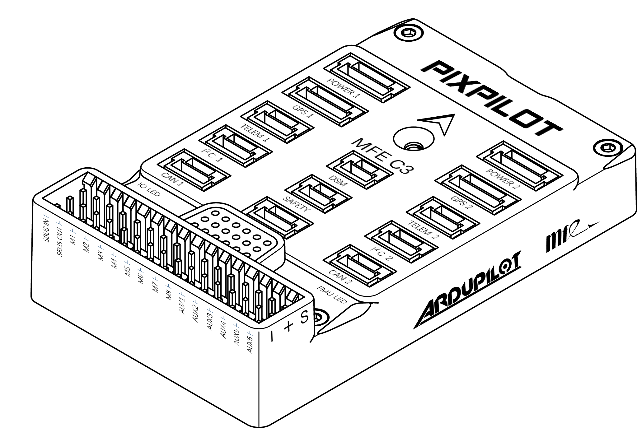
Pinouts
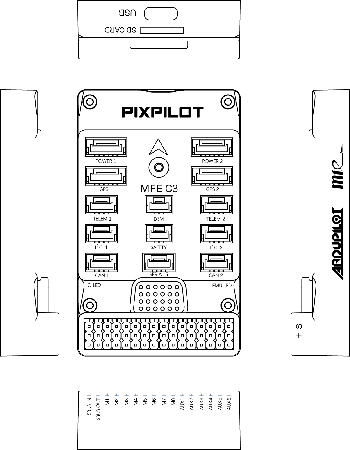
Connector pin assignments
TELEM1, TELEM2 ports
| Pin | Signal | Volt |
|---|---|---|
| 1 | VCC | +5V |
| 2 | TX (OUT) | +3.3V |
| 3 | RX (IN) | +3.3V |
| 4 | GND | GND |
I2C1, I2C2 ports
| PIN | SIGNAL | VOLT |
|---|---|---|
| 1 | VCC | +5V |
| 2 | SCL | +3.3V |
| 3 | SDA | +3.3V |
| 4 | GND | GND |
CAN1, CAN2 ports
| PIN | SIGNAL | VOLT |
|---|---|---|
| 1 | VCC | +5V |
| 2 | CAN_H | +12V |
| 3 | CAN_L | +12V |
| 4 | GND | GND |
Safety port
| PIN | SIGNAL | VOLT |
|---|---|---|
| 1 | VCC | +5V |
| 2 | LED | +5V |
| 3 | SAFKEY | +5V |
GPS1/I2C1, GPS2/I2C2 ports
| PIN | SIGNAL | VOLT |
|---|---|---|
| 1 | VCC | +5V |
| 2 | TX | +3.3V |
| 3 | RX | +3.3V |
| 4 | SCL | +3.3V |
| 5 | SDA | +3.3V |
| 6 | GND | GND |
Serial5 port
| Pin | Signal | Volt |
|---|---|---|
| 1 | VCC | +5V |
| 2 | TX (OUT) | +3.3V |
| 3 | RX (IN) | +3.3V |
| 4 | GND | GND |
Power1, Power2 ports
| PIN | SIGNAL | VOLT |
|---|---|---|
| 1 | VCC | +5V |
| 2 | VCC | +5V |
| 3 | CURRENT | +3.3V |
| 4 | VOLTAGE | +3.3V |
| 5 | GND | GND |
| 6 | GND | GND |
DSM ports
| PIN | SIGNAL | VOLT |
|---|---|---|
| 1 | VCC | +3.3V |
| 2 | RX | +3.3V |
| 3 | GND | GND |
RC Input
The SBus input pin, which by default is mapped to a timer input, can be used for all ArduPilot supported receiver protocols, except CRSF/ELRS and SRXL2 which require a true UART connection. However, FPort, when connected in this manner, will only provide RC without telemetry.
To allow CRSF and embedded telemetry available in Fport, CRSF, and SRXL2 receivers, a full UART, such as SERIAL4 (UART8) would need to be used for receiver connections. Below are setups using UART4. SERIAL4_PROTOCOL should be set to “23”.
FPort would require SERIAL4_OPTIONS be set to “15”.
CRSF would require SERIAL4_OPTIONS be set to “0”.
SRXL2 would require SERIAL4_OPTIONS be set to “4” and connects only the UART4 TX pin.
Any UART can be used for RC system connections in ArduPilot also, and is compatible with all protocols except PPM. See Radio Control Systems for details.
PWM Output
The PixPilot-V3 supports up to 14 PWM outputs. First first 8 outputs (labelled S1 to S8) are controlled by a dedicated STM32F103 IO controller. These 8 outputs support all PWM output formats, but not DShot.
The remaining 6 outputs (labelled AUX1 to AUX6) are the “auxiliary” outputs. These are directly attached to the STM32F427 and support all PWM protocols as well as DShot.
All 14 PWM outputs have GND on the top row, 5V on the middle row and signal on the bottom row.
The 8 main PWM outputs are in 3 groups:
PWM 1 and 2 in group1
PWM 3 and 4 in group2
PWM 5, 6, 7 and 8 in group3
The 6 auxiliary PWM outputs are in 2 groups:
PWM 1, 2, 3 and 4 in group1
PWM 5 and 6 in group2
Channels within the same group need to use the same output rate. If any channel in a group uses DShot then all channels in the group need to use DShot.
Battery Monitor Settings
These should already be set by default. However, if lost or changed:
Enable Battery monitor with these parameter settings :
BATT_MONITOR =4
Then reboot.
BATT_VOLT_MULT 18.0
BATT_AMP_PERVLT 24.0
BATT2_VOLT_MULT 18.0
BATT2_AMP_PERVLT 24.0
DroneCAN capability
There are 2 CAN ports which allow connecting two independant CAN bus outputs. Each of these can have multiple CAN peripheral devices connected.
Loading Firmware
The board comes pre-installed with an ArduPilot compatible bootloader, allowing the loading of xxxxxx.apj firmware files with any ArduPilot compatible ground station.
Firmware for these boards can be found here in sub-folders labeled “PixPilot-C3”.