MAUCH Power Monitor
This page explains how to set up the MAUCH power monitors HS-050-xx* (50A), HS-100-xx (100A) and HS-200-xx* (200A) to measure battery voltage and current consumption. For information on purchasing, please see the MAUCH Electronics website.
(*xx is the indicator for: LV = Vow Voltage 2-6S, maximum 28V HV = High Voltage 4-14S, maximum 60V).
Tip
These monitors use a hall-effect current sensor. These are much more accurate across the whole current range than sensors using a shunt resistor, consume very little power, and are unaffected by operating temperature.
Overview
MAUCH has a number of PMs, which are compatible with Pixhawk, APM, Pixhawk lite, AUAV-X2, and CUAV Pixhack. The sensors boards are capable of delivering 100A continuous current for HS-100-V2 and 200A for the HS-200-V2 (without any time limit). The maximum burst current is 1200A@25’C and 800A@85’C for 1 second.
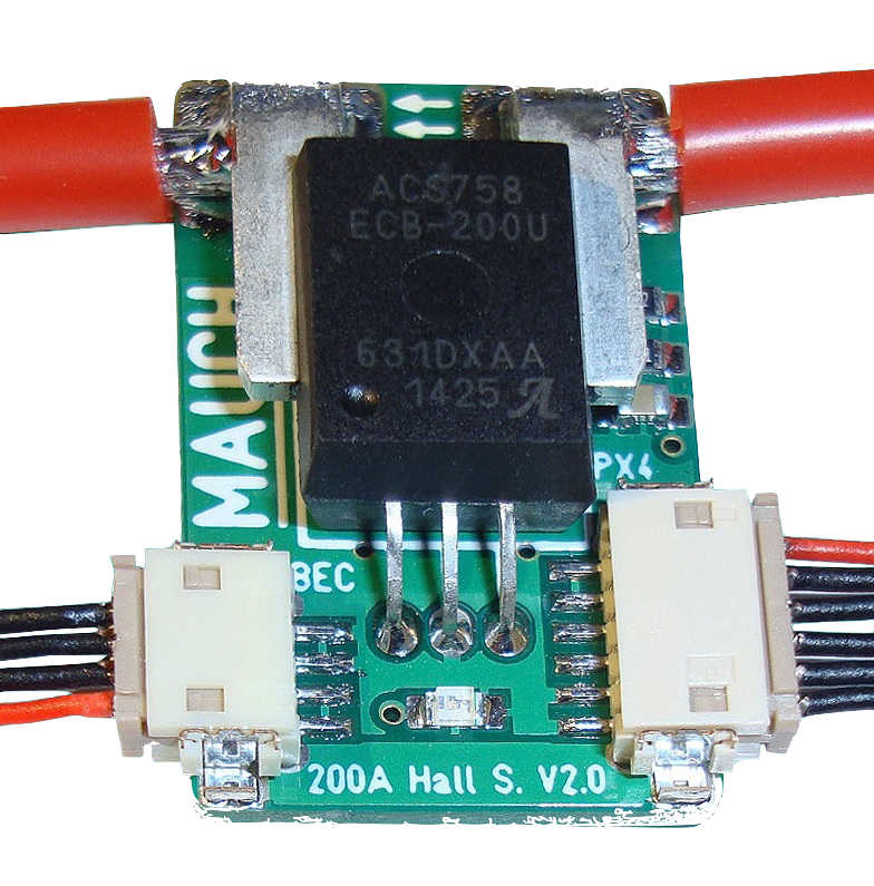
MAUCH Power Monitor
Sensor Board:
Current sensor is a “true hall sensor” up to 50A (HS-050-LV/HV),100A (HS-100-LV/HV) or 200A (HS-200- LV/HV)
Continuous current 200A for HS-200-xx and 100A for HS-050-xx / HS-100-xx
Over current: 1200A@25’C or 900A@85’C (all sensors)
Ultra-low noise power supply (LP2985-4.0) for current sensor and offset shifting circuit.
Microchip MCP601 operational amplifier for offset shifting.
LiPo voltage measurement with 1% resistor divider in factor 9:1 (LV) and 18:1 (HV)
Supply voltage to Pixhawk / APM = 5.35V/3A (with attached LV- or HV-BEC)
Bright LED as power on indicator (blue LED for 200A / green LED for 100A / yellow for 50A)
2x10cm / AWG12 cable soldered to current sensor as standard size (Up to AWG8 possible).
Low Voltage: 2-6S BEC
Input 2-6S LiPo / max. 28V
Output 5.35V / 3A -> +/- 0.05V –> Ripple 10mV (0.2%) at 1.5A output current.
Input wrong polarity protection, as well as Panasonic FM 220uF/35V input capacitor to prevent burn out.
10cm 4 pole silicone cable to sensor board with DF-13 connector.
47mm x 18mm x 11mm / 8g with cables and shrinking tube.
High Voltage: 4-14S HYB-BEC
Input: 4S-14S LiPo / max, 60VOutput: 5.3V / 3A -> +/- 0.05V -> Ripple 80uV (0.00008V) at 1.5A output current.
Panasonic FM input capacitors to prevent burn out.
10cm 4 pole silicone cable to sensor board with DF-13 connector.
53mm x 21mm x 14mm / 20g with cables and shrinking tube.
There is more information about hall current sensors and these PMs in this blog post: Safety First: 100A & 200A Hall Sensor with BEC for Pixhawk / APM.
Connecting the PM to an autopilot board
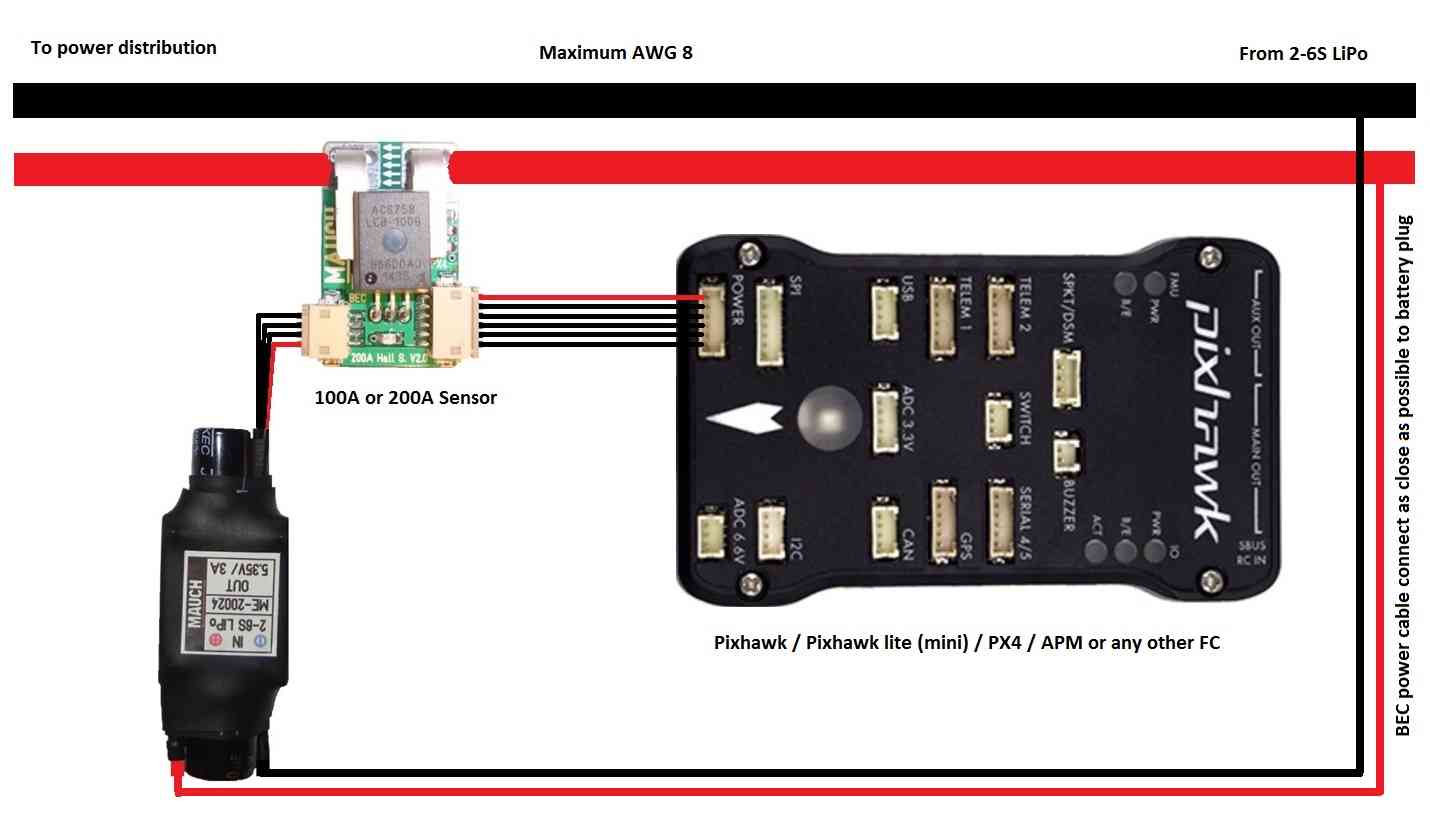
MAUCH Power Module, BEC, PixhawkWiring
Setup through Mission Planner
Power Monitor Configuration in Mission Planner explains in more detail how to configure a Power Module and get low battery alerts from Mission Planner.
The MAUCH PM’s are not available in the Sensor selection list (at time of writing) so you will need to select Other and perform a manual calibration. Because the PM uses hall sensors you can ignore the recommendation to calibrate the sensor at >3Amps.
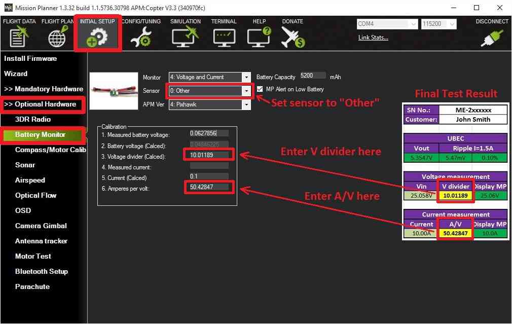
Each sensor board comes with an final test result, which indicates the calibration values for voltage and current measurement.
On the Mission Planner’s INITIAL SETUP | Optional Hardware | Battery Monitor screen set the Sensor to Other.
Enter the voltage divider from the final test result and press TAB or click out of the field. Then the calculated battery voltage should be within a few millivolt of the actual battery voltage.
Enter the Amperes per volt from the final test result (A/V) and press TAB or click out of the field.
MissionPlanner: Battery Monitor Configuration for MAUCH Power Monitor