AutoTune
The AutoTune for tradheli is completely different from multicopter AutoTune. It can tune any combination of feedforward (ATC_RAT_xxx_FF),
the rate gains (ATC_RAT_xxx_P and ATC_RAT_xxx_D), or angle P gain (ATC_ANG_xxx_P). The tuning for rate gains begins with finding the maximum allowable value for the rate gains and then tunes them. Knowing the maximum value enables the AutoTune feature to keep from creating an instability.
Before you start AutoTune, you must:
Reduce the vibrations in the control signals as low as possible
On a calm day, the heli will maintain a near driftless hover (< 1 m/s)
This will greatly improve your chances at a successful AutoTune.
The following video covers the steps described in this wiki page.
Parameter Descriptions
Tune Sequence Bitmask
User can specify the tuning desired using the AUTOTUNE_SEQ parameter. Individual gain tuning or combination of tuning several gains can be specified using the bitmask. Rate P and Rate D are conducted together and always preceded with determining max gains allowable.
Bits |
Values |
||||||||||||||||||||||||||||||||
|---|---|---|---|---|---|---|---|---|---|---|---|---|---|---|---|---|---|---|---|---|---|---|---|---|---|---|---|---|---|---|---|---|---|
|
|
** Max gain determination is always done before tuning Rate D and Rate P gains. This test determines the maximum allow values of ATC_RAT_xxx_D & ATC_RAT_xxx_P so that the helicopter never experiences servere oscillations due to raising these gains too high. Since the maximum allowable values of ATC_RAT_xxx_D & ATC_RAT_xxx_P are found, tuning is done by incrementing these gains by 5% of their maximum allowable value.
Axes Bitmask
The AUTOTUNE_AXES parameter specifies one or more axes to be tuned.
Bits |
Values |
||||||||||||||||||||||||
|---|---|---|---|---|---|---|---|---|---|---|---|---|---|---|---|---|---|---|---|---|---|---|---|---|---|
|
|
Maximum Response Gain
The AUTOTUNE_GN_MAX parameter specifies the maximum response gain to be used to tune the Rate D, Rate P and Angle P gains. The response gain is the output of the response divided by the input. It is recommended that 1.8 to 2.0 be used for pitch and roll axes as these axes are typically more lightly damped. It is recommended that 1.0 to 1.4 be used for the yaw axis.
Minimum Test Frequency
The AUTOTUNE_FRQ_MIN parameter specifies the minimum frequency in radians per second used during the dwell or frequency sweeps. For frequency sweeps, this will be the starting frequency. The default value is good for helicopters with rotor diameters less than 1.4 meters.
Maximum Test Frequency
The AUTOTUNE_FRQ_MAX parameter specifies the maximum frequency in radians per second used during the dwell or frequency sweeps. For frequency sweeps, this will be the ending frequency. The default value is fine for helicopters with rotor diameters greater than 1.2 meters. Consider raising to 100 radians/sec for helicopters with rotor diameters less then 1.2 meters.
Velocity P Gain
The AUTOTUNE_VELXY_P parameter specifies P gain for velocity feedback. This aids the AutoTune in maintaining aircraft position during the frequency sweeps and dwells. It does not apply to ATC_RAT_xxx_FF tuning. Keep this at 0.1 unless the aircraft is drifting more than 10 meters during the dwell and frequency sweeps. It only affects position holding while the aircraft is oscillating during these tests. If it does drift more than 10 meters during the dwell adn frequency sweep tests then increase this parameter but don’t increase much beyond 0.2. In between the oscillations, it may drift if the aircraft wasn’t properly trimmed for hover. This gain will not help with that.
Preparing for AutoTune
Ensure you complete all of the items in the Preparing for Tuning wiki page.
Transmitter Setup
Be sure to put the AutoTune flight mode as one of the flight modes on your transmitter flight mode switch. You don’t want to be reaching for the GCS to switch out of the AutoTune if your heli is not behaving properly. You want to be able to switch modes instantly.
AutoTune Flights
Suggested Tuning Sequence
In any axis, it is recommended to conduct the feedforward gain tuning first, then the Rate D and Rate P gain tuning, and lastly the Angle P tuning. Don’t try to tune every axis in one flight, it could take up to 10-15 min to tune one axis. Here is a suggested flights and tuning sequence. Conventional helicopters do not need Yaw feedforward tuning, therefore the gain can be set to zero. Dual helicopters may require Yaw feedforward tuning.
Flight |
Parameter |
Value |
|---|---|---|
1 |
3 (Roll and Pitch) |
|
1 (feedforward) |
||
2 |
2 (Pitch) |
|
2 (Rate D and Rate P) |
||
1.8 |
||
3 |
1 (Roll) |
|
2 (Rate D and Rate P) |
||
1.8 |
||
4 |
3 (Roll and Pitch) |
|
4 (Angle P) |
||
1.8 |
||
5 |
4 (Yaw) |
|
2 (Rate D and Rate P) |
||
1.0 |
||
6 |
4 (Yaw) |
|
4 (Angle P) |
||
1.8 |
Tuning Flight Procedures
When conducting an AutoTune flight, be sure to have at least at 50 meter by 50 meter area to fly. The aircraft will move during the autotuning process. Do not let the aircraft get too far away.
Caution
During the feedforward test, the aircraft may travel 5-10 meters, and perhaps even further with larger helicopters. You may have to bring it back after each iteration of the tuning test.
Power up the controller.
Set the flight mode to either stabilize or AltHold (Althold recommended).
Enable motor interlock and allow rotors to complete runup.
Lift off and establish stable hover approximately 3-5 meters above the ground.
Switch into AutoTune and center all sticks.
AutoTune will start conducting the maneuvers.
Note
If you don’t see anything happening, verify your sticks are centered.
After the tuning is complete, a message will appear in the GCS saying “AutoTune complete”.
To test the settings, switch out of AutoTune and then back to AutoTune and you will be able to test the settings that were tuned.
Once you are finished testing, descend and land in AutoTune. Once the aircraft has landed, the engine will shutdown on its own. At that point flip your motor interlock switch to disabled and disarm the aircraft.
Note
Aircraft must be disarmed in the AutoTune flight mode to save the gain settings.
Tuning Maneuver Descriptions
ATC_RAT_xxx_FF Tuning
The
ATC_RAT_xxx_FFtuning is accomplished by achieving a constant angular rate of 50 deg/s and determining the steady state command required to maintain the 50 deg/s. The maneuver to achieve the constant angular rate consists of changing attitude by 15 deg in one direction then reversing direction to achieve a constant rate of 50 deg/s before reaching 15 deg in the opposite direction. Finally it returns to the starting attitude. DuringATC_RAT_xxx_FFtuning there is no position holding logic and the aircraft may drift, reposition the aircraft between maneuvers as needed to keep it from drifting. Making any inputs during this test will stop the tuning and won’t begin again unless the sticks are centered. The following video demonstrates theATC_RAT_xxx_FFtuning.
ATC_RAT_xxx_D and ATC_RAT_xxx_P Tuning
ATC_RAT_xxx_DandATC_RAT_xxx_Ptuning starts with determining the maximumATC_RAT_xxx_DandATC_RAT_xxx_Pgains that can be safely tuned. A frequency sweep is conducted from the AUTOTUNE_FRQ_MIN to AUTOTUNE_FRQ_MAX. This determines the approximate frequency required for calculating the maximum allowable gains. A series of dwells (oscillations at one frequency) are completed to more accurately determine the data required to calculate the maximum allowableATC_RAT_xxx_DandATC_RAT_xxx_Pgains. Next another frequency sweep is conducted to approximate the frequency for tuningATC_RAT_xxx_Dgain. Then theATC_RAT_xxx_Dgain is raised until the response gain stops decreasing. Next theATC_RAT_xxx_Pgain is increased until the response gain exceeds the AUTOTUNE_GN_MAX. During this tuning, you can’t make any inputs to hold position during the tuning however the logic includes position holding during the test maneuver but not between manuevers. If you make any inputs, then it will stop the tuning and wait until you center the sticks before it begins again. The aircraft will drift very little during the maneuver. If it is drifting more than 10 meters during the maneuver then the Velocity P Gain can be increased to minimize drifting. In between the oscillation maneuvers, it may drift if the aircraft wasn’t properly trimmed for hover. The Velocity P Gain gain will not help with that. The tuning sweeps are 23 seconds in duration. The following video demonstrates theATC_RAT_xxx_DandATC_RAT_xxx_Ptuning.
ATC_ANG_xxx_P Tuning
ATC_ANG_xxx_Ptuning starts with conducting a frequency sweep from from the AUTOTUNE_FRQ_MIN to AUTOTUNE_FRQ_MAX. This determines the approximate frequency for the maximum response gain. Then dwells (oscillations at one frequency) are conducted to tune theATC_ANG_xxx_Pgain. The gain is raised or lowered to determine theATC_ANG_xxx_Pgain that corresponds to a response gain (output angle/input angle request) that matches AUTOTUNE_GN_MAX. During this tuning, you can’t make any inputs to hold position during the tuning however the logic includes position holding during the test maneuver but not between manuevers. If you make any inputs, then it will stop the tuning and wait until you center the sticks before it begins again. If it is drifting more than 10 meters during the maneuver then the Velocity P Gain can be increased to minimize drifting. In between the oscillation maneuvers, it may drift if the aircraft wasn’t properly trimmed for hover. The Velocity P Gain gain will not help with that. The tuning sweeps are 23 seconds in duration.
Max Gain Determination
This test determines the maximum
ATC_RAT_xxx_DandATC_RAT_xxx_Pgains that can be safely tuned. A frequency sweep is conducted from the AUTOTUNE_FRQ_MIN to AUTOTUNE_FRQ_MAX. This determines the approximate frequency required for calculating the maximum allowable gains. A series of dwells (oscillations at one frequency) are completed to more accurately determine the data required to calculate the maximum allowableATC_RAT_xxx_DandATC_RAT_xxx_Pgains. The maximum allowable gains are provided in a GCS message. Although these are termed maximum allowable gains, it is not recommended that these gains be used without any buildup as they would most likely cause feedback oscillations. Experience has shown thatATC_RAT_xxx_Dgains up to 25-35% of the maximum allowable value can be used safely andATC_RAT_xxx_Pgains of up to 50% of the maximum allowable gain can be used safely. If you make any inputs, then it will stop the gain determination test and wait until you center the sticks before it begins again. The aircraft will drift very little during the maneuver. If it is drifting more than 10 meters during the maneuver then the Velocity P Gain can be increased to minimize drifting. In between the oscillation maneuvers, it may drift if the aircraft wasn’t properly trimmed for hover. The Velocity P Gain gain will not help with that. The frequency sweeps are 23 seconds in duration.
Tune Check
This test allows the user to look at the final tune in the frequency domain. It consists of one frequency sweep to obtain the frequency domain data that can be viewed in the log file. If you make any inputs during the frequency sweep, then it will stop the tune check test and wait until you center the sticks before it begins again, starting the sweep over. The aircraft will drift very little during the maneuver. If it is drifting more than 10 meters during the maneuver then the Velocity P Gain can be increased to minimize drifting. The frequency sweeps are 23 seconds in duration.
Log Analysis
ATC_RAT_xxx_FF Tuning
After completing the ATC_RAT_xxx_FF tuning, the log should be reviewed to ensure the code determined the value of ATC_RAT_xxx_FF gain correctly. Unless head speed is very low, this gain should not be above 0.3. The graph below shows a time history of the target and actual rates for a FF tuning test.
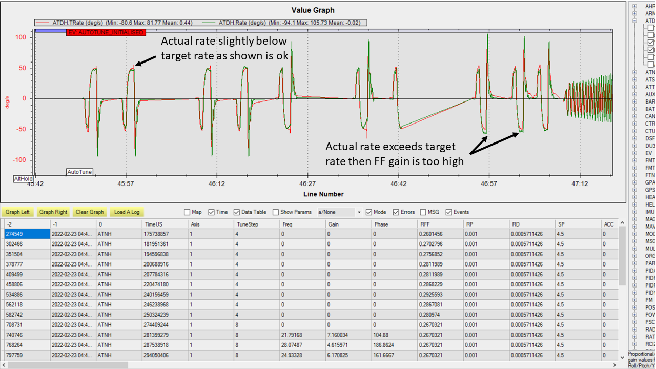
In the time history, an example of a good capture of the FF gain is shown the pitch up part of the tuning. The actual rate is slightly below the target as it reaches the steady state. Next the pitch down FF tuning is conducted and it can be seen that the rate appears to drop off before achieving steady state. The FF gain is increased but it can be seen that the actual rate exceeds the target which results in the FF gain being too high. If you see behavior like this, it is best to take the FF gain found where the rate is slightly below the target rate and manually enter it for the ATC_RAT_xxx_FF gain.
The video discusses what to look for in the log.
ATC_RAT_xxx_D and ATC_RAT_xxx_P Tuning
After completing the ATC_RAT_xxx_D and ATC_RAT_xxx_P tuning, the log should be reviewed to ensure the gains were determined correctly. If the ATC_RAT_xxx_D gain is zero after tuning, it can be adjusted manually by finding the max allowable gain provided in the GCS messages found in the bin log file. Use 10% of the gain provided as rate_d given at the end of the max gain test. The messages look like this
AutoTune: Max rate P freq=23.62473 gain=6.239318 AutoTune: ph=161.0000 rate_p=0.121300 AutoTune: Max Rate D freq=41.98507 gain=1.493140 AutoTune: ph=251.0000 rate_d=0.012072
Therefore in this case, a value for ATC_RAT_xxx_D of 0.0012 could be manually entered and also manually change ATC_RAT_xxx_P to zero. Then run the autotune test again. If ATC_RAT_xxx_D gain has not changed from the value manually entered accept the tuned values and move on to ATC_ANG_xxx_P tuning.
The most common problem that may be experienced with the ATC_RAT_xxx_P tuning is the Maximum Response Gain may be set too low. It may require viewing the log to determine the highest response gain. Then set the Maximum Response Gain higher but don’t exceed 2.2 as the response could have larger overshoots when capturing an attitude.
The video discusses what to look for in the log.
ATC_ANG_xxx_P Tuning
After completing the ATC_ANG_xxx_P tuning, the log should be reviewed to ensure the gains were determined correctly. Be sure to set the Maximum Response Gain slightly higher than the value used for the ATC_RAT_xxx_D and ATC_RAT_xxx_P tuning, maybe 10% higher. In this tuning, the frequency where the max response gain occurs is determined in the frequency response. Then the ATC_ANG_xxx_P gain is raised or lowered to achieve the desired response gain at the frequency where the maximum response gain occurs. Below is an example of the frequency sweep from the ATC_ANG_xxx_P tuning.
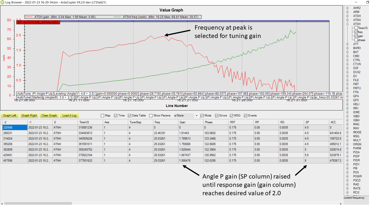
In this example, the response gain (ATSH.gain) has a peak shown in the graph. The table below shows the dwells completed after the frequency sweep where the ATC_ANG_xxx_P was raised until the response gain met the Maximum Response Gain value which was 2.0 in this case. It is important to ensure that the correct frequency was found. In cases like tuning the yaw axis, the response gain may not have a peak and a low frequency may be chosen which will not result in a proper tuning of the gain. In this case, the ATC_ANG_xxx_P gain may be manually set higher by 1. So if the starting value was 4.5 then manually set it to 5.5 and run the ATC_ANG_xxx_P tuning again.