Note
Refer to this page if you’re using a version earlier than 4.1.
Soaring
The autonomous soaring functionality in ArduPilot allows the plane to respond to rising air current (thermals) in order to extend endurance and gain altitude with minimal use of the motor (soaring). Its full technical description is available in
S. Tabor, I. Guilliard, A. Kolobov. ArduSoar: an Open-Source Thermalling Controller for Resource-Constrained Autopilots. International Conference on Intelligent Robots and Systems (IROS), 2018.
Note
Use of an airspeed sensor is strongly recommended in order to obtain optimum performance. Use without a sensor could yield unsatisfactory results. Consistent operation without an airspeed sensor is a pending future development.
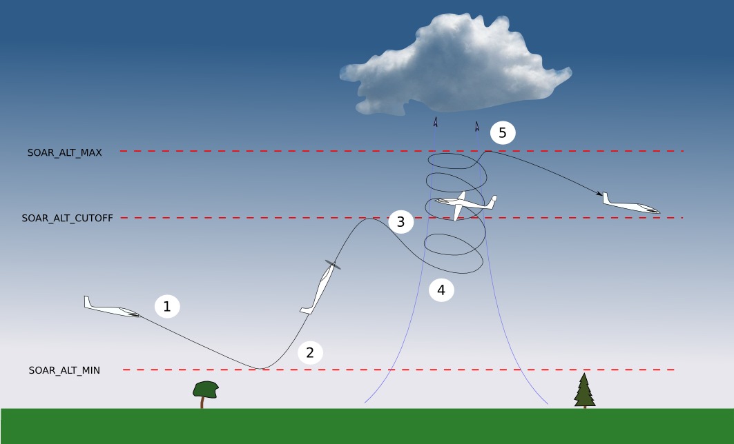
This picture shows the different phases of flight when using the soaring functionality:
If modes AUTO, FBWB or CRUISE are entered, and Soaring is enabled, the throttle is set to zero provided the aircraft is above SOAR_ALT_MIN altitude and the aircraft then begins gliding.
If the aircraft descends to SOAR_ALT_MIN altitude, throttle is re-enabled and the aircraft will begin to climb to the altitude of the next waypoint, in AUTO, or to SOAR_ALT_CUTOFF altitude in CRUISE or FBWB. In AUTO, if the waypoint altitude is less than SOAR_ALT_CUTOFF altitude, then Soaring can not begin before reaching the waypoint. If it is above SOAR_ALT_CUTOFF altitude, then Soaring can occur once that altitude has been reached.
When the aircraft reaches SOAR_ALT_CUTOFF altitude, throttle is set to zero again.
If, during gliding flight, the air is estimated to be rising at more than SOAR_VSPEED and the RC switch position allows it, the aircraft will automatically enter THERMAL mode. While in THERMAL mode the aircraft will adjust the circling position to better centre the thermal.
THERMAL mode is exited under the following conditions:
SOAR_ALT_MAX is reached.
SOAR_ALT_MIN is reached.
Flight mode is changed by the pilot.
The estimate of achievable climb rate falls below SOAR_VSPEED, and thermalling has lasted at least SOAR_MIN_THML_S seconds.
The aircraft drifts more than SOAR_MAX_DRIFT - see Limit maximum distance from home
The flight mode will be returned to whatever it was before THERMAL was triggered.
Airspeed Control
When in SOARING, the target airspeed while cruising is set via throttle stick position for FBWB and CRUISE modes, even while gliding. For AUTO mode, it is set at AIRSPEED_CRUISE, unless the SOAR_CRSE_ARSPD parameter is set to a non-zero value (“0” is default). If it is set to “-1”, then the Speed to fly computed value will be used. If greater than zero, then that value in meters/sec will be used for target airspeed.
While in THERMAL mode, the target airspeed will be AIRSPEED_CRUISE, unless the SOAR_THML_ARSPD parameter is set to a non-zero value (“0” is default). Then that value in meters/sec will be used for target airspeed instead.
Hardware
To use your plane for soaring, it should ideally be a glider type aircraft with a good lift to drag ratio and be equipped with an airspeed sensor.
Generally all boards support soaring, except those with firmware limitations referred to on this page. As of June 2020 non-supported boards include:
KakuteF7Mini
KakuteF7
sparky2
Pixhawk1-1M
OMNIBUSF7V2
Setup
Mission
The main requirement for a mission is that it take the aircraft above SOAR_ALT_CUTOFF so that gliding flight is initiated. To achieve this, set the waypoints’ altitude(s) above SOAR_ALT_CUTOFF.
Soaring Parameters
Enable
Set the parameter SOAR_ENABLE to 1 and refresh the parameters. This will allow the other SOAR parameters to appear in the GCS.
Drag Polar
To work out how fast the air is rising or sinking the autopilot needs to know the aircraft’s sink rate for a given airspeed in still air. This is related to the drag polar of the plane and is specified using the SOAR_POLAR parameters. SOAR_POLAR_K is the most important one to set initially and is calculated using the following formula:
SOAR_POLAR_K = 16*Weight/Area (weight in kg, area in metres squared).
SOAR_POLAR_K = 703*Weight/Area (weight in oz, area in inches squared).
Calculating the other parameters is explained under tuning.
RC switch (Optional)
You can use a 3-position RC switch to control when the autopilot can use soaring. Set the parameter RCX_OPTION parameter for the desired channel to SOAR (index 88) - see Auxiliary Functions. The 3 positions have the following effect.
Low. Soaring is disabled (equivalent to setting SOAR_ENABLE = 0). Throttle will be used as normal. Switching to this from either of the positions below, will disable Soaring and maintain the current flight mode.
Mid. Soaring will have control over throttle. The mode will not automatically change to THERMAL based on detected rising air. However, when manually set to THERMAL mode using RC controller or GCS, the autopilot will try to follow rising air currents. It will still restore the previous mode if the aircraft is not climbing, or if it drifts too far (see below).
High. Fully automatic mode changes to THERMAL from AUTO, FBWB or CRUISE modes in response to detected rising air, and following of rising air currents.
Position |
PWM Value |
Auto throttle cutoff |
Tracking thermal updrafts |
Automatic change back from THERMAL |
Automatic change to THERMAL |
Low |
< 1500 us |
N |
N |
N |
N |
Mid |
1500 - 1700 us |
Y |
Y |
Y |
N |
High |
> 1700 us |
Y |
Y |
Y |
Y |
When in THERMAL mode, changing the switch position between Mid and High positions commands exiting thermalling and restoring the previous mode.
When climbing back to altitude under throttle, changing the switch position to Low and back aborts the climb and starts gliding.
Set limits
Because the soaring feature can follow rising air as required to gain altitude, it is important to set limits to avoid it leaving the original flight area completely. This is especially important in windy conditions as the autopilot will try to follow thermals downwind. There are three ways to set limits.
Altitude limits
SOAR_ALT_MAX sets the altitude you want the autopilot to stop thermalling. SOAR_ALT_MIN sets the minimum altitude you want the autopilot to descend to while gliding.
Spatial limits
The parameter SOAR_MAX_DRIFT can be used to limit how far (in metres) the aircraft can drift while in THERMAL mode. If the aircraft reaches this limit in THERMAL mode, it will revert to the original flight mode.
If the original flight mode was FBWB or CRUISE mode, the drift distance is measured from the location THERMAL was entered.
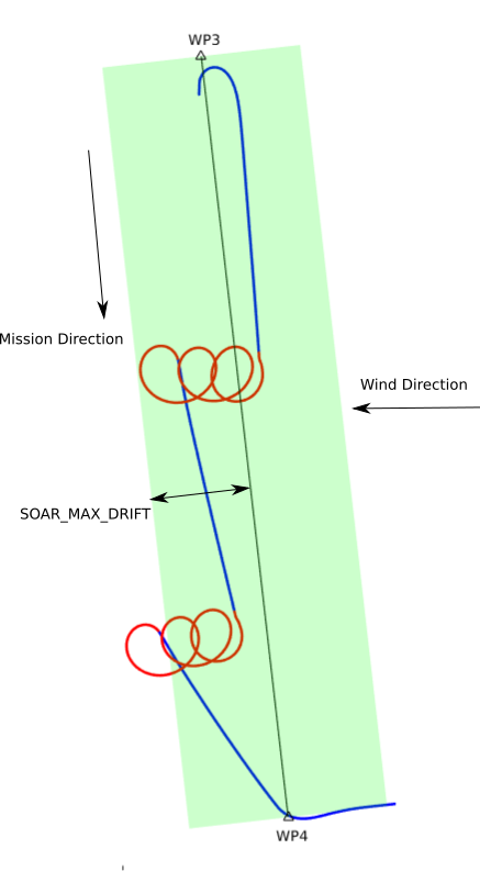
If the original flight mode was AUTO mode, the drift distance is measured from the closest point on the mission segment to where THERMAL was entered. Drift sideways or backwards, but not along the original mission track, is counted. This allows thermalling to continue if the wind is moving the aircraft in the direction of the next waypoint.
The image below shows a scenerio where the mission track is north to south and the wind is causing thermals to drift east to west. The aircraft will follow them but will respect SOAR_MAX_DRIFT. Note that sometimes it will go a little beyond SOAR_MAX_DRIFT as it lines up its heading to the next waypoint before reverting to AUTO mode.
If using FBWB or CRUISE mode, the parameter SOAR_MAX_RADIUS can be used to trigger RTL if the aircraft is more than this distance from home when in THERMAL mode. Note that this parameter won’t stop the aircraft from exceeding this distance before it enters THERMAL mode.
Geofence can be used as a last line of defence. Set it up in the usual way.
Tuning
Triggering lift
SOAR_VSPEED controls when the mode will be changed to THERMAL. The default of 0.7m/s may be too low if you fly in strong conditions. Increasing this value makes the aircraft more “picky” about the lift it will try to circle in.
Thermalling bank angle
The parameter SOAR_THML_BANK sets the bank angle when thermalling. 30 - 45 degrees works well depending on the size of the thermals in your area.
If the aircraft is not achieving this average bank angle when thermalling, you should check -
that the limiting bank angle ROLL_LIMIT_DEG is set a bit larger than SOAR_THML_BANK (note the units are different) to give some room for manoeuvring;
that the navigation parameter NAVL1_PERIOD is no larger than the time needed for a complete turn at the specified bank angle.
Drag Polar
While the default settings for SOAR_POLAR_B and SOAR_POLAR_CD0 should be OK for most foamie-style glider aircraft, improving the accuracy of these parameters will improve how your aircraft detects and centres lift. You can use this spreadsheet to calculate better values from glide tests.
Time hysteresis
Adding hysteresis can reduce the frequency of mode changes.
SOAR_MIN_THML_S: Minimum time to remain in THERMAL once entered for a thermal before exiting due to low lift or altitude limits.
SOAR_MIN_CRSE_S: Minimum time to remain in glide after exiting THERMAL due to low lift or altitude limits before entering mode again, or when entering Soaring initially.
TECS Tuning
Note
In firmware revisions before 4.1, it was necessary to set TECS_SPDWEIGHT to 2.0 when using soaring. This is now handled automatically.
For best results the TECS needs to be set up to fly the aircraft at a consistent airspeed when gliding.
If your aircraft has trouble maintaining airspeed accurately you can tune it by confirming that TECS_SPDWEIGHT is set to 2.0, SOAR_ENABLE to 1 and set SOAR_VSPEED to a large number, say 50.0, or use the RC switch to inhibit mode changes. This means that the aircraft will glide but will never begin thermalling. Set SOAR_ALT_CUTOFF to an altitude high enough to allow a good length of time to be spent gliding.
Launch the aircraft and put it in AUTO mode. It should climb to SOAR_ALT_CUTOFF
and then begin a gliding descent. Watch the telemetry graphs or look at the Dataflash logs after the flight. Is the aircraft maintaining the demanded airspeed? The actual and demanded airspeed can be seen in the onboard log as
TECS.sp and TECS.spdem, and via telemetry you can use NAV_CONTROLLER_OUTPUT.aspd_error. Problems can usually be fixed
by increasing PTCH2SRV_IMAX and TECS_INTEG_GAIN to achieve good airspeed
tracking in gliding flight.
Speed to Fly Feature
Notes
MAVLINK Telemetry
Currently, the only effect on telemetry is that when soaring is active the climb rate item (VFR_HUD.climb) is altered. Rather that the estimated vertical speed of the aircraft, the estimated vertical speed of the air mass is sent. This field is used by Mission Planner and OpenTX radios to produce vario audio output.
Use of TECS synthetic airspeed
If your plane can’t accommodate an airspeed sensor, it is possible to use the TECS synthetic airspeed estimate TECS_SYNAIRSPEED. Make sure you read the warning regarding this feature before deciding to use it. To use this feature, set the parameter TECS_SYNAIRSPEED to 1.