Downloading and Analyzing Data Logs in Mission Planner
Dataflash logs are stored on the autopilot and can be download after a flight. By default, they are created after you first arm the vehicle. This topic explains how to configure and access Dataflash logs.
Depending on the autopilot type and configuration, the dataflash logs may be saved on a SD card, dataflash chip or streamed over MAVLink telemetry ports. The MAVLink option does require a high-speed telemetry port, typically 921600 baud.
Note
Telemetry logs (also known as “tlogs”) collect similar information to dataflash logs (see Diagnosing problems using Logs for more information).
Note
If your vehicle is having trouble producing dataflash logs - including the infamous “No IO heartbeat” diagnostic message - try a different SD card. You may also choose to test the card using a dedicated tool, such as H2testw. Low board voltages are also known to cause logging issues.
Logging Parameters
Some commonly used parameters are:
LOG_BACKEND_TYPE: Bitmask for where to save logs to. Common values are “0” to disable logging, “1” (bit 0 set) to log to SD card file, “2”(bit 1 set) to stream over MAVLink and “4”(bit 2 set) to log to board dataflash memory, if equipped.
LOG_BITMASK: Bitmask for what items are logged. Normally, use default value, or “0” to disable logging.
LOG_DISARMED: Setting to 1 will start logging when power is applied, rather than at the first arming of the vehicle. Useful when debugging pre-arm failures. Setting to 2 will only log on power application other than USB power to prevent logging while setting up on the bench. Setting to 3 will also erase any log in which the vehicle does not proceed to the armed stated. This prevents accumulating numerous logs while configuring on the bench or at the field. See LOG_DARM_RATEMAX also for managing log file sizes while logging disarmed.
LOG_FILE_DSRMROT: Setting this bit will force the creation of a new log file after disarming, waiting 15 seconds, and then re-arming. Normally, a log will be one file for every power cycle of the autopilot, beginning upon first arm.
LOG_FILE_MB_FREE: This parameter sets the minimum free space on the logging media before logging begins. If this is not available, then older logs will be deleted to provide it during initialization. Default is 500MB.
LOG_FILE_RATEMAX: This sets the maximum rate that streaming log messages will be logged to the file backend to limit file sizes. A value of zero(default) means no limit is applied to normal logging, which depends on the SCHED_LOOP_RATE value ( 50Hz: Plane, 300Hz: QuadPlane/Rover, 400Hz: Copter, normally). Note that similarly, LOG_BLK_RATEMAX and LOG_MAV_RATEMAX perform the same optional limiting for the BLOCK logging and MAVLink logging streams, respectively.
LOG_MAX_FILES: The maximum number of log file that will be written on dataflash or SD card before starting to rotate log number. Limit is a maximum of 500 logs.
Note
If you suspect that you are missing logging entries due to excessive logging speed, you can check the DSF.Dp log message for the amount of missed entries.
Note
Logging of the continuously streaming log messages, such as attitude, sensors, etc. can be paused by using the RCx_OPTION auxiliary function “164” on a transmitter channel. Switching this channel high will pause these messages, but not events, mode changes, warnings, etc. This allows autopilots with limited logging capabilites (ie using Block logging to chip memory and no SD card) to log only when desired during the flight, as during tuning phases or determination of TECs parameters, etc. You can also eliminate unneeded log messages using LOG_BITMASK to reduce log size
Replay Logging
ArduPilot has the ability to log in a fashion that solutions to EKF/AHRS issues can be more easily verified by actually re-playing a log against code changes to see if the solution results in the desired, corrected behavior. This requires that the logs showing the issue to be worked on be made with logging active during disarmed periods (with LOG_DISARMED set to a non-zero value, preferably 3) and LOG_REPLAY =1 , thereby logging more sensor data than normal.
SD Card Logging Issues
If you are running into problems with bad logging errors on SD cards, here are some things you can try.
Format the card to FAT32 or vFAT (newer formats can work with new versions of Ardupilot and better hardware).
Perform a full format to check for bad sectors.
Check that the card is not write protected.
Check card contacts.
Some cards are problematic, try using a different one.
Ensure that the card is fast enough to keep up with logging demands (Class 10 works for many, but lower speeds can work too).
Reduce the amount of data included with the logs in LOG_BITMASK.
Incrementally increase BRD_SD_SLOWDOWN up to a maximum of 32 (default is 0).
On-Board DataFlash Logging
Some boards do not have SD card interfaces for logging, but rather a limited amount of dataflash, typically 16MB. This saves log files in a manner like a circular buffer. Once the flash is filled, the oldest log file is overwritten with the current logging data. If there is only one file on the flash when space runs out, logging is stopped instead.
A new log file will be started after boot, upon arming, or, immediately if LOG_DISARMED is 1.
If LOG_FILE_DSRMROT is enabled, any disarm will stop logging and a new file started upon the next arm or immediately if LOG_DISARMED is 1. Otherwise, logging to the current file will resume on a re-arm. Any reboot stops logging to the current file.
In order to maximize the utility of the limited flash space several things can be done:
Reduce the things logged using LOG_BITMASK.
Eliminate logging the EKF3 messages which are voluminous and usually needed only for problem diagnosis using the EK3_LOG_LEVEL parameter.
Only log when needed during the flight, ie tuning, gathering data for TECS tuning, etc. using an RC Aux switch set to “164” to start and stop log writes.
Reduce the logging rate to a slower rate (below 10Hz) by setting LOG_BLK_RATEMAX which is by default unrestricted.
Download and erase the logs each flight and only log one file for a flight
Note
some dataflash chips are particularly slow, leading to gaps in the logs. Setting LOG_BLK_RATEMAX to a lower value can help eliminate these gaps.
Downloading logs via MAVLink
Connect your vehicle to the ground station using the micro USB cable
Open the Mission Planner’s Flight Data screen
On the bottom left, select the “DataFlash Logs” tab and push the “Download DataFlash Log Via Mavlink” button
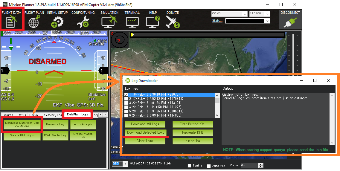
Then, select the log you want to download. This will save that log to your MissionPlanner/logs directory, in a folder named after the vehicle type, such as QUADCOPTER.
Automatic Analysis of logs

Mission Planner: Start LogAnalysis
The simplest analysis is to generate a basic automated report that will highlight common problem areas. For that, click on “Log Analysis” and select a log that you’ve already saved to the MissionPlanner/logs directory. They will be in folders named after the vehicle type, such as QUADCOPTER or ROVER. Once you pick the log you want, it will generate a report that looks like this:

Manually review a log
For more detailed analysis, click on “Review a Log” and select a log that you’ve already saved to the MissionPlanner/logs directory. Once again, they will be in folders named after the vehicle type, such as QUADCOPTER or ROVER.
Steps to review a log downloaded from the internet, or your vehicle
For DataFlash logs, with a .bin or .log extension:
Download the log file. Note the place on your computer to which it is downloaded. (For example, it might be C:\Downloads)
Open Mission Planner
Navigate to the “Flight Data” page (top left)
Select the “Dataflash Logs” tab (mid-screen, left side)
Select the “Review a Log” button.
A standard Windows “select a file” box will let you go find the .bin file that you downloaded, at the place that you downloaded it. (Per the example above, it is in C:\Downloads) Choose that file.
After reading the log, a Manual Log Review window will be open, which allows you to plot data from the log for inspection. (see below)
Reviewing the log data
Once you pick the log you want, you will get charts such as the below. The basic format of the dataflash is:
Line numbers appear on the very left side of the viewer
Software version and board type appear at the top
FMT messages are next which tell the mission planner the column headers for each message type
PARM rows which show each parameter (in the order in which they appear in the eeprom) along with their value at the beginning of the flight
Flight data messages including GPS, IMU, etc.
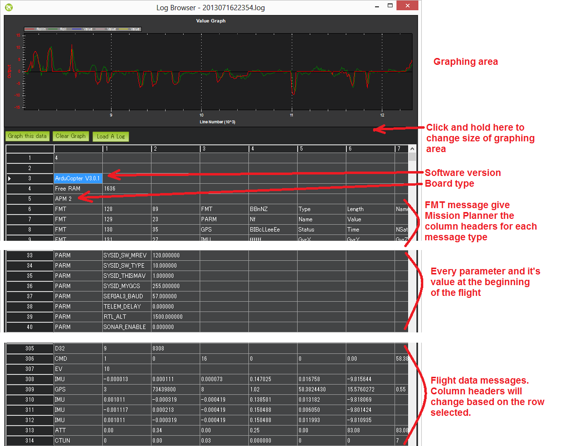
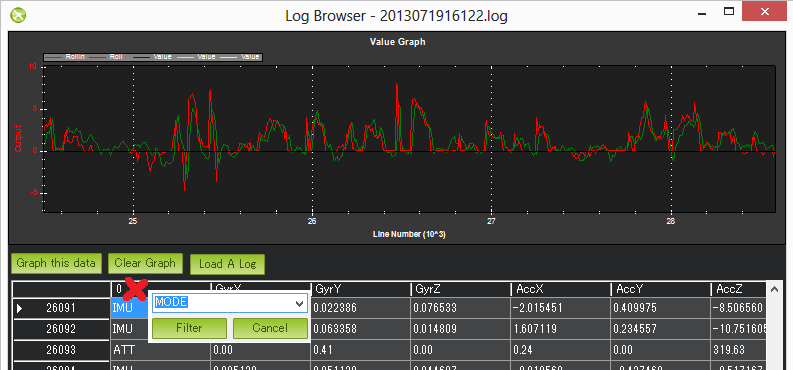
Graph any flight data by first clicking on the appropriate row, you should see the column headers update appropriately. Next find the column you wish to graph, click on it and then push the “Graph this data” button. In the example above the ATT’s Roll-In and Roll data have been graphed. The mouse’s scroll wheel can be used to zoom in or out. You may also select an area of the graph to zoom in on it. Zoom out by right-mouse-button clicking and selecting “Set Scale to Default”. Here’s a mini tutorial on using this feature. You may also filter on just the first column (the flight data message type) by clicking on the first column and selecting the message type from the drop-down. This is very useful especially for viewing the different flight modes (called “MODE” messages) used during the mission. Click the first column again but press “Cancel” to clear the filter.
Setting what data you want recorded
The LOG_BITMASK parameter controls what messages are recorded in the logs. The bits differ between vehicles. The image above is for Copter.

Bitmask Table (Plane)
Bit |
BitMask Name |
What is logged if bit is set |
|---|---|---|
0 |
Fast Attitude |
Attitude @ 25Hz |
1 |
Medium Attitude |
Attitude @ 10Hz |
2 |
GPS |
GPS |
3 |
System Performance |
CPU,etc. Performance monitoring |
4 |
Control Tuning |
Control Data |
5 |
Navigation Tuning |
Navigation Data |
7 |
IMU |
IMU (ACC/Gyro) Data |
8 |
Mission Commands |
Mission/GCS Commands |
9 |
Battery Monitor |
Battery Monitors data |
10 |
Compass |
Compasses Data |
11 |
TECS |
Speed/Height Controller Data |
12 |
Camera |
Camera Data (if present) |
13 |
RC Input & Output |
RC input/Servo output data |
14 |
Rangefinder |
Rangefinder Data (if present) |
19 |
Raw IMU |
Raw IMU data, unprocessed |
20 |
Full Rate Attitude |
Attitude at SCHED_LOOP_RATE |
21 |
Video Stabilization |
GyroFlow Data logs |
ATTITUDE logging will occur at highest rate of the selections.
Note
the logging of EKF3 data is controlled by the EK3_LOG_LEVEL parameter.
Message Details (Copter specific)
Note
Many messages are detailed in the Onboard Message Log Messages page in each vehicle’s wiki section.
ATT (attitude information):
DesRoll |
The pilot’s desired roll angle in degrees (roll left is negative, right is positive) |
Roll |
The vehicle’s actual roll in degrees (roll left is negative, right is positive) |
DesPitch |
The pilot’s desired pitch angle in degrees (pitch forward is negative, pitch back is positive) |
Pitch |
The vehicle’s actual pitch angle in degrees (pitch forward is negative, pitch back is positive) |
DesYaw |
The pilot’s desired heading in degrees with 0 = north |
Yaw |
The vehicle’s actual heading in degrees with 0 = north |
ErrRP |
The average size of the roll/pitch error estimate (values between 0 and 1) |
ErrYaw |
The average size of the yaw error estimate (values between 0 and 1) |
ATUN (auto tune overview):
Axis: 0 = Roll, 1 = Pitch |
|
TuneStep |
0 = Returning towards Level (before or after a test), 1 = Testing (i.e. performing a twitch to test response), 2 = Updating gains (twitch completed and gains adjusted) |
RateMin |
Minimum recorded rate during this test |
RateMax |
Maximum recorded rate during this test |
RPGain |
Rate P gain value being tested |
RDGain |
Rate D gain value being tested |
SPGain |
Stabilize P gain being tested |
ATDE (auto tune step details):
Angle |
Angle of the copter in centi-degrees for the axis being testedx |
Rate |
Rate of rotation of the copter for the axis being tested |
CAM (time and position when camera shutter was activated):
GPSTime |
The GPS reported time since epoch in milliseconds |
Lat |
The accelerometer + GPS latitude estimate |
Lng |
The accelerometer + GPS longitude estimate |
Alt |
The accelerometer + barometer estimated altitude in cm above ground |
Roll |
The vehicle roll angle in centi-degrees |
Pitch |
The vehicle pitch angle in centi-degrees |
Yaw |
The vehicle’s heading in centi-degrees |
CMD (commands received from the ground station or executed as part of a mission):
CTot |
The total number of commands in the mission |
CNum |
This command’s number in the mission (0 is always home, 1 is the first command, etc) |
CId |
|
Copt |
The option parameter (used for many different purposes) |
Prm1 |
The command’s parameter (used for many different purposes) |
Alt |
The command’s altitude in meters |
Lat |
The command’s latitude position |
Lng |
The command’s longitude position |
COMPASS (raw compass, offset and compassmot compensation values):
Field |
Description |
MagX, MagY. MagZ |
Raw magnetic field values for x, y and z axis |
OfsX, OfsY, OfsZ |
Raw magnetic offsets (will only change if COMPASS_LEARN parameter is 1) |
MOfsX, MOfsY, MOfsZ |
Compassmot compensation for throttle or current |
CURRENT (battery voltage, current and board voltage information):
FIELD |
DESCRIPTION |
Thr |
Pilot input throttle from 0 ~ 1000 |
ThrInt |
Integrated throttle (i.e. sum of total throttle output for this flight) |
Volt |
Battery voltage in volts * 100 |
Curr |
Current drawn from the battery in amps * 100 |
Vcc |
Board voltage |
CurrTot |
Total current drawn from battery |
CTUN (Control, Throttle and altitude information):
FIELD |
DESCRIPTION |
TimeUS |
Time stamp for messages in microseconds (can be ignored) |
ThI |
The pilot’s throttle in as a number from 0 to 1000 |
ABst |
Angle Boost: throttle increase (from 0 ~ 1000) as a result of the copter leaning over (automatically added to all pilot and autopilot throttle to reduce altitude loss while leaning) |
ThO |
Final throttle output sent to the motors (from 0 ~ 1000). Normally equal to ThrI+ABst while in stabilize mode. |
ThH |
Estimated throttle required to hover throttle in the range 0 ~ 1 |
DAlt |
The Desired Altitude while in AltHold, Loiter, RTL or Auto flight modes. It is influenced by EKF origin, which in 3.5.X is corrected by GPS altitude. This behaviour is turned off in 3.6.X and can be turned on with EKF_OGN_HGT_MASK. |
Alt |
The current EKF Altitude |
BAlt |
Barometer Altitude: The altitude above ground according to the barometer |
DSAlt |
Desired distance in cm from ground or ceiling (only visible if Sonar is available) |
SAlt |
Sonar Altitude: the altitude above ground according to the sonar (Only visible of Sonar is available) |
TAlt |
Terrain altitude (not used by default) |
DCRt |
Desired Climb Rate in cm/s |
CRt |
Climb Rate in cm/s |
N |
Harmonic notch current center frequency for gyro in Hz |
D32, DU32 (single data values which are either signed 32bit integers or unsigned 32bit integers):
FIELD |
DESCRIPTION |
id |
Identification number for the variable. There are only two possible values:
|
EKF (Extended Kalman Filter):
Log information here (Dev Wiki). Overview here.
ERR (an error message):
SubSystem and Error codes listed below
| Subsys | ECode and Description |
|---|---|
| 2 = Radio |
|
| 3 = Compass |
|
| 5 = Radio Failsafe |
|
| 6 = Battery Failsafe |
|
| 8 = GCS Failsafe |
|
| 9 = Fence Failsafe |
|
| 10 = Flight mode Change failure | Vehicle was unable to enter the desired flight mode normally because of a bad position estimate |
| 11 = GPS |
|
| 12 = Crash Check |
|
| 13 = Flip mode | 2 = Flip abandoned (not armed, pilot input or timeout) |
| 15 = Parachute |
|
| 16 = EKF Check |
|
| 17 = EKF Failsafe |
|
| 18 = Barometer |
|
| 19 = CPU Load Watchdog |
|
| 20 = ADSB Failsafe |
|
| 21 = Terrain Data | 2 = missing terrain data |
| 22 = Navigation |
|
| 23 = Terrain Failsafe |
|
| 24 = EKF Primary changed |
|
| 25 = Thrust Loss Check |
|
| 26 = Sensor Failsafe (Sub) |
|
| 27 = Leak Failsafe (Sub) |
|
| 28 = Pilot Input Timeout Failsafe (Sub only) |
|
| 29 = Vibration Failsafe |
|
EV: (an event number). The full list of possible events can be found in AP_Logger.h but the most common are:
Event No |
DESCRIPTION |
10 |
Armed |
11 |
Disarmed |
15 |
Auto Armed (pilot has raised throttle above zero and autopilot is free to take control of throttle) |
18 |
Land Complete |
25 |
Set Home (home location coordinates have been capture) |
28 |
Not Landed (aka Takeoff complete) |
GPA: (Global Position Accuracy)
FIELD |
DESCRIPTION |
VDop |
Vertical dilution of precision, a unitless measure of precision https://en.wikipedia.org/wiki/Dilution_of_precision |
HAcc |
Horizontal Accuracy as reported by the GPS module, in meters |
VAcc |
Vertical Accuracy as reported by the GPS module, in meters |
SAcc |
Speed accuracy as reported by the GPS, in m/s/s |
VV |
|
SMS |
The autopilot time in milliseconds that the accuracy/GPS position data is associated with. |
Delta |
The time between when the previous GPS message and the current GPS message was parsed by the autopilot, in milliseconds |
GPS:
FIELD |
DESCRIPTION |
Status |
0 = no GPS, 1 = GPS but no fix, 2 = GPS with 2D fix, 3 = GPS with 3D fix |
Time |
The GPS reported time since epoch in milliseconds |
NSats |
The number of satellites current being used |
HDop |
A measure of gps precision (1.5 is good, >2.0 is not so good) https://en.wikipedia.org/wiki/Dilution_of_precision |
Lat |
Latitude according to the GPS |
Lng |
Longitude according to the GPS |
RelAlt |
Accelerometer + Baro altitude in meters |
Alt |
GPS reported altitude (not used by the autopilot) |
SPD |
Horizontal ground speed in m/s |
GCrs |
Ground course in degrees (0 = north) |
IMU (accelerometer and gyro information):
FIELD |
DESCRIPTION |
GyrX, GyrY, GyrZ |
The raw gyro rotation rates in radians/second |
AccX, AccY, AccZ |
The raw accelerometer values in m/s/s |
Mode (flight mode):
FIELD |
DESCRIPTION |
Mode |
The flight mode displayed as a string (i.e. STABILIZE, LOITER, etc) |
ThrCrs |
Throttle cruise (from 0 ~ 1000) which is the autopilot’s best guess as to what throttle is required to maintain a stable hover |
Rsn |
Reason for mode change (TX command, failsafe, etc) . The meaning of code values can be found in ModeReason |
NTUN (navigation information):
FIELD |
DESCRIPTION |
WPDst |
Distance to the next waypoint (or loiter target) in cm. Only updated while in Loiter, RTL, Auto. |
WPBrg |
Bearing to the next waypoint in degrees |
PErX |
Distance to intermediate target between copter and the next waypoint in the latitude direction |
PErY |
Distance to intermediate target between copter and the next waypoint in the longitude direction |
DVelX |
Desired velocity in cm/s in the latitude direction |
DVelY |
Desired velocity in cm/s in the longitude direction |
VelX |
Actual accelerometer + gps velocity estimate in the latitude direction |
VelY |
Actual accelerometer + gps velocity estimate in the longitude direction |
DAcX |
Desired acceleration in cm/s/s in the latitude direction |
DAcY |
Desired acceleration in cm/s/s in the longitude direction |
DRol |
Desired roll angle in centi-degrees |
DPit |
Desired pitch angle in centi-degrees |
PM (performance monitoring):
FIELD |
DESCRIPTION |
NLon |
Number of long running main loops (i.e. loops that take more than 20% longer than they should according to SCHED_LOOP_RATE - ex. 3ms for 400Hz rate) |
NLoop |
The total number of loops since the last PM message was displayed. This allows you to calculate the percentage of slow running loops (which should never be higher than 15%). Note that the value will depend on the autopilot clock speed |
MaxT |
The maximum time that any loop took since the last PM message. This shouldn’t exceed 120% of scheduler loop period, but will be much higher during the interval where the motors are armed |
Mem |
Available memory, in bytes |
Load |
Percentage (times 10) of the scheduler loop period when CPU is used |
RCOUT (pwm output to individual RC outputs):
RC1, RC2, etc : pwm command sent from autopilot to the esc/motor/RC output
Viewing KMZ FILES
When you download the dataflash log files from the autopilot it will automatically create a KMZ file (file with extension .kmz). This file can be opened with Google Earth (just double click the file) to view your flight in Google Earth. Please see the instructions on the Telemetry Logs Page for additional details.