Sensor Position Offset Compensation
ArduPilot includes compensation for sensor placement on the vehicle. This page clarifies what parameters can be set and how they should be set.
Note
In most vehicles which have all their sensors (IMU, GPS, optical flow, etc) within 15cm of each other, it is unlikely that providing the offsets will provide a noticeable performance improvement.
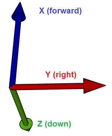
The sensor’s position offsets are specified as 3 values (X, Y and Z) which are distances in meters from the IMU (which can be assumed to be in the middle of the autopilot board) or the vehicle’s center of gravity.
X : distance forward of the IMU or center of gravity. Positive values are towards the front of the vehicle, negative values are towards the back.
Y : distance to the right of the IMU or center of gravity. Positive values are towards the right side of the vehicle, negative values are towards the left.
Z : distance below the IMU or center of gravity. Positive values are lower, negative values are higher.
In practice the distance to the sensor can be measured from the center of the autopilot unless the autopilot itself is placed a significant distance from the vehicle’s center of gravity in which case the IMU position offsets can be specified and then the other sensor’s position offsets can be specified from the vehicle’s center of gravity.
Parameter Details
IMU (aka INS):
For the best results the autopilot (and thus the IMUs) should be placed at the center-of-gravity of the vehicle but if this is physically impossible the offset can be partially compensated for by setting the following parameters.
INS_POS1_X, INS_POS1_Y, INS_POS1_Z the first IMU’s position from the vehicle’s center-of-gravity
INS_POS2_X, INS_POS2_Y, INS_POS2_Z the second IMU’s position from the vehicle’s center-of-gravity
INS_POS3_X, INS_POS3_Y, INS_POS3_Z the third IMU’s position from the vehicle’s center-of-gravity
The compensation is only partial because ArduPilot can correct the vehicle’s velocity and position estimate but it does not correct the acceleration estimate. For example if the autopilot was placed on the nose of a vehicle and the vehicle suddenly leans back (i.e. rotates so that its nose points up) with no offset compensation the vehicle velocity estimate would momentarily show the vehicle is climbing when it’s not. With the position offsets added the velocity would not show this momentary climb. The EKF would still show a momentary vertical acceleration and because we use the acceleration in our altitude hold controllers this could still lead to the vehicle momentary reducing throttle.
Although individual position offsets can be set for each IMU, the difference between the placement of IMUs on most autopilot boards is so small that the same values can be used for all IMUs
Note
if the IMU offset is specified, then all the following offsets are relative to Center of Gravity rather than the IMU.
GPS:
GPS1_POS_X, GPS1_POS_Y, GPS1_POS_Z the first GPS’s position from the vehicle’s IMU or center-of-gravity
GPS2_POS_X, GPS2_POS_Y, GPS2_POS_Z the second GPS’s position from the vehicle’s IMU or center-of-gravity
Range Finder (Sonar or Lidar):
RNGFND1_POS_X, RNGFND1_POS_Y, RNGFND1_POS_Z the first RangeFinder’s position from the vehicle’s IMU or center of gravity
RNGFND2_POS_X, RNGFND2_POS_Y, RNGFND2_POS_Z the second RangeFinder’s position from the vehicle’s IMU or center of gravity
Optical Flow:
FLOW_POS_X, FLOW_POS_Y, FLOW_POS_Z distance from the IMU or center of gravity
Visual Odometry:
VISO_POS_X, VISO_POS_Y, VISO_POS_Z distance from the IMU or center of gravity